My "FUNstock MAX" has arrived!
My "FUNstock MAX" has arrived!
I'm giddy! The day I get the Rostock from UPS (yesterday afternoon) is the day I unload my i3 Printer (for a profit!) to help make up what I spent here. SADLY, I will not be able to touch it until monday as I have prior commitments to do over the weekend  . I will put up pics and any issues i might have along the way, as i go along. Hopefully I can video a print by late month (Work, kids, etc...). And YES, I've already named him. Hopefully he won't be lazy and inconsistent like my brother
Re: My "FUNstock MAX" has arrived!
On page 20 of the new manual the idler assy needs 4 washers. Are the washers to on either side of the idler assy? My screw only goes halfway thru the locknut with 4 washers...

Re: My "FUNstock MAX" has arrived!
I'm pretty sure that's four washers per tri-support, not four washers per idler. The washers go next to the screw head and next to the nut, as they spread the load on the melamine.m4r1n5 wrote:On page 20 of the new manual the idler assy needs 4 washers. Are the washers to on either side of the idler assy? My screw only goes halfway thru the locknut with 4 washers...
Re: My "FUNstock MAX" has arrived!
Thanx! I've gotten to pge 24, but its my weekend so I'm going to put more than an hour in to it today. I'll post pics soon.
Re: My "FUNstock MAX" has arrived!
Page 51, to make sore, does not need to worry which wire goes where concerning the stop switches. black can go on either ends.
-
foshon

- Printmaster!
- Posts: 600
- Joined: Fri Mar 08, 2013 3:05 pm
- Location: Just to the right of SeeMeCNC
Re: My "FUNstock MAX" has arrived!
Right!m4r1n5 wrote:Page 51, to make sore, does not need to worry which wire goes where concerning the stop switches. black can go on either ends.
Purple = sarcasm
Please do a board search before posting your question, many have been answered with very time consuming detail already.
Please do a board search before posting your question, many have been answered with very time consuming detail already.
Re: My "FUNstock MAX" has arrived!
After a break, I figured now is a good time to show some pics!
[img]http://i1326.photobucket.com/albums/u65 ... d5d2b9.jpg[/img]
Packed up Nicely!
[img]http://i1326.photobucket.com/albums/u65 ... ca50d8.jpg[/img]
Out and ready to go.
[img]http://i1326.photobucket.com/albums/u65 ... d5d2b9.jpg[/img]
Packed up Nicely!
[img]http://i1326.photobucket.com/albums/u65 ... ca50d8.jpg[/img]
Out and ready to go.
Re: My "FUNstock MAX" has arrived!
[img]http://i1326.photobucket.com/albums/u65 ... 2747ff.jpg[/img]
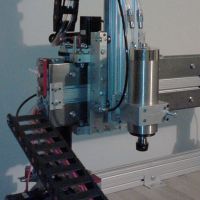
It started out slow. But once I got in the flow of the manual, I picked up the pace in this area of the build
[img]http://i1326.photobucket.com/albums/u65 ... 74ebe1.jpg[/img]
THIS area took some Eye coordination, gentle touch, and a LARGE mallet...... just kidding!....... din't need the gentle touch. Ha
Re: My "FUNstock MAX" has arrived!
[img]http://i1326.photobucket.com/albums/u65 ... 38eb7a.jpg[/img]
Leveling these things was a Bear! OH, also I pulled my Lazy Susan off the dining table and put the printer on it. SOOO much easier than having to either walk around the thing constantly, or wear out the feet turning this thing!
[img]http://i1326.photobucket.com/albums/u65 ... 54567b.jpg[/img]
THEN I realized the top ends were too thick, so I had to file them down a bit.
Last edited by m4r1n5 on Sun Jun 16, 2013 8:10 am, edited 1 time in total.
Re: My "FUNstock MAX" has arrived!
[img]http://i1326.photobucket.com/albums/u65 ... b001a0.jpg[/img]
I cut the excess plastic off the rear of this because it ws too tight when connected to the stopswitch.
I cut the excess plastic off the rear of this because it ws too tight when connected to the stopswitch.
Re: My "FUNstock MAX" has arrived!
[img]http://i1326.photobucket.com/albums/u65 ... f18f75.jpg[/img]
I used the plastic method for the band, but needed tape to make it work. Also, I suspended the brackets with string to better to the belts on. I'm up to this point but I'm short some screws for the clamps, so I have to go buy some .
.
I used the plastic method for the band, but needed tape to make it work. Also, I suspended the brackets with string to better to the belts on. I'm up to this point but I'm short some screws for the clamps, so I have to go buy some
Re: My "FUNstock MAX" has arrived!
QUESTION...when soldering on the LCD board area, is it important that the solders do not touch other pins, or is it ok? I'm not good at this and some of my pins are connected through the solder
[img]http://i1326.photobucket.com/albums/u65 ... 889fe4.jpg[/img]
[img]http://i1326.photobucket.com/albums/u65 ... 889fe4.jpg[/img]
Re: My "FUNstock MAX" has arrived!
Correct. Remove the excess solder and make sure the adjacent pc board pads do not touch each other with solder. Also make sure you get a good connection between the pin sticking through and the pad.m4r1n5 wrote:QUESTION...when soldering on the LCD board area, is it important that the solders do not touch other pins, or is it ok? I'm not good at this and some of my pins are connected through the solder

Re: My "FUNstock MAX" has arrived!
I am not the electronics guru, but I'm pretty sure this is a bad thing. Each connection should be separate. You can still salvage this board. Just use a solder pump to remove the first try and you get a do over. A lower wattage, very thin soldering iron will help here.
solder pump link: http://www.amazon.com/Desoldering-Vacuu ... ering+pump
Soldering iron(reasonable price): http://www.amazon.com/Soldering-Station ... ron+solder
Excellent link posted by foshon: http://www.youtube.com/watch?v=I_NU2ruzyc4
Hope this helps
solder pump link: http://www.amazon.com/Desoldering-Vacuu ... ering+pump
Soldering iron(reasonable price): http://www.amazon.com/Soldering-Station ... ron+solder
Excellent link posted by foshon: http://www.youtube.com/watch?v=I_NU2ruzyc4
Hope this helps
-"Simpler is better, except when complicated looks really cool."
-"As soon as you make something fool proof...along comes an idiot."
-"I have not failed. I've just found 10,000 ways that won't work." ~Thomas Edison
-"As soon as you make something fool proof...along comes an idiot."
-"I have not failed. I've just found 10,000 ways that won't work." ~Thomas Edison
Re: My "FUNstock MAX" has arrived!
solder should look something like this,
- Attachments
-
My rostock build log http://forum.seemecnc.com/viewtopic.php?f=42&t=1228
Re: My "FUNstock MAX" has arrived!
[img]http://i1326.photobucket.com/albums/u65 ... 9e3be7.jpg[/img]
My problem, aside from barely any exp., was I used the one on the right..so I bought the one on the left. Batt powered but works well. I couldn't undo what I did, so I had to take a blade to it. SAD, I know, but the only way I knew how.
[img]http://i1326.photobucket.com/albums/u65 ... 6896f1.jpg[/img]
BUUUT, I did much better with the proper tool.
[img]http://i1326.photobucket.com/albums/u65 ... 1c429e.jpg[/img]
Re: My "FUNstock MAX" has arrived!
I didn't find a Hobbed gear in my inventory so I had to skip that and move on until I call up and get one sent.
I'm getting ready to install the hot end, might do some tomorrow. Between work and kids, I don't get much sleep to begin with. So far though its been fun watching this thing go up.
QUESTION... The thermistor in the center of the Onyx bed. Is that supposed to just hang there unattached to anything? I read the manual (pge 100 & 101) and found no other instructions after the kapton tape suggestion. Is it just supposed to hang there?
-
Eaglezsoar

- ULTIMATE 3D JEDI
- Posts: 7159
- Joined: Sun Apr 01, 2012 5:26 pm
Re: My "FUNstock MAX" has arrived!
Pages 100 and 101 tell you to insert the thermistor into the hole and place RTV Silicone around it. When the Silicone dries you are supposed to solder the leads from the thermistor to the hotbed.m4r1n5 wrote:I didn't find a Hobbed gear in my inventory so I had to skip that and move on until I call up and get one sent.
I'm getting ready to install the hot end, might do some tomorrow. Between work and kids, I don't get much sleep to begin with. So far though its been fun watching this thing go up.
QUESTION... The thermistor in the center of the Onyx bed. Is that supposed to just hang there unattached to anything? I read the manual (pge 100 & 101) and found no other instructions after the kapton tape suggestion. Is it just supposed to hang there?
Two things could be wrong here, you are reading but not understanding or you have the wrong version of the manual. On page 101 at the top of the page it should say The Rostock MAX Assembly Guide, 2
nd Edition. If yours does not say second edition on it then download the latest one at http://www.geneb.org/rostock-max/Rostoc ... -Guide.pdf.
Make sure you read and UNDERSTAND what you are reading. The complete instructions on how to connect the thermistor to the hotbed are on pages 100-101 that's why I don't understand how you can say there are no other instructions
after the Kapton tape suggestion. Make sure you have revision 2 of the manual and make sure you download the latest Abobe Reader. You are missing something but not to worry we will figure it out. Let me know when you can read the
rest of the pages 100 and 101, I want to make sure your reader is working and you have the correct manual. Get back to me and let me know. It is very important that you do not miss steps.
Re: My "FUNstock MAX" has arrived!
Ouch.. I'd be very surprised if that board still works. It looks like you cut a bunch of traces on the circuit board when you tried to undo your solder bridges.m4r1n5 wrote:, so I had to take a blade to it. SAD, I know, but the only way I knew how.
[img]http://i1326.photobucket.com/albums/u65 ... 6896f1.jpg[/img]
You should have either a) used solder braid, b) used a solder sucker/vacuum tool or c) let someone with more experience soldering fix it for you.
The yellow soldering iron probably would have worked fine if you got a smaller tip for it.
Re: My "FUNstock MAX" has arrived!
My bad, read it again and saw the "solder to the pads" in there. I guess thats what the pink arrows were pointing to and not the wires. All good, just take me another 30 min to fix up.Two things could be wrong here, you are reading but not understanding or you have the wrong version of the manual. On page 101 at the top of the page it should say The Rostock MAX Assembly Guide, 2
nd Edition. If yours does not say second edition on it then download the latest one at http://www.geneb.org/rostock-max/Rostoc ... -Guide.pdf.
Make sure you read and UNDERSTAND what you are reading. The complete instructions on how to connect the thermistor to the hotbed are on pages 100-101 that's why I don't understand how you can say there are no other instructions
after the Kapton tape suggestion. Make sure you have revision 2 of the manual and make sure you download the latest Abobe Reader. You are missing something but not to worry we will figure it out. Let me know when you can read the
rest of the pages 100 and 101, I want to make sure your reader is working and you have the correct manual. Get back to me and let me know. It is very important that you do not miss steps.
Re: My "FUNstock MAX" has arrived!
Ouch.. I'd be very surprised if that board still works. It looks like you cut a bunch of traces on the circuit board when you tried to undo your solder bridges.
You should have either a) used solder braid, b) used a solder sucker/vacuum tool or c) let someone with more experience soldering fix it for you.
The yellow soldering iron probably would have worked fine if you got a smaller tip for it.
Thanks for brightening my day. Ill probably order one just in case then.
-
Eaglezsoar
- ULTIMATE 3D JEDI
- Posts: 7159
- Joined: Sun Apr 01, 2012 5:26 pm
Re: My "FUNstock MAX" has arrived!
m4r1n5, I am glad that you found the information. Please make sure you read and understand what you are reading. The information you need is in the manual but if there is something you do not understand, please leave us a message
on this forum. We would rather you contact us a lot rather than make a mistake and create problems for yourself. We are here to help you at all times.
Have a great build!
on this forum. We would rather you contact us a lot rather than make a mistake and create problems for yourself. We are here to help you at all times.
Have a great build!
Re: My "FUNstock MAX" has arrived!
I'm pretty much done with putting the printer together. However, I'm having issues with the hot end thermister popping out as I'm plugging in the wires or moving around The hot end . Once that's done I will be able to start using the software. I will add pics later on tonight As I am on my phone right now. I'm very excited to see it actually move! All this work kama hope everything runs right.
Re: My "FUNstock MAX" has arrived!
Make sure you secure the thermistor VERY WELL. You do not want it to pop out during a print or else very very very bad things will happen, i.e. melted hot end and potential for fire.
Re: My "FUNstock MAX" has arrived!
Would it be safe to wrap that area of the hotend in kapton tape as well as having the RTV on there?ApacheXMD wrote:Make sure you secure the thermistor VERY WELL. You do not want it to pop out during a print or else very very very bad things will happen, i.e. melted hot end and potential for fire.