Rostock Max V2 + Upgrades | Build thread

Start your own build thread so others can see how it's going, and even help out!
ZenOhSix
Printmaster!
Posts: 64
Joined: Tue Aug 25, 2015 6:58 pm

Rostock Max V2 + Upgrades | Build thread

Post by ZenOhSix »

Hello!

This will be my build thread, whereas I will upload pictures detailing my progress. I know many others have done the same thing, but I always find these types of threads very useful when making purchasing decisions or building something myself. Further, as I print items - I will post them in here (like the Architect thread), allowing others to see the quality, time required, or failures encountered.

My Background:
This is my first 3D Printer. I have absolutely no experience with 3D printing, or any CAD software alike. I decided to get into 3D printing for a few different reasons:
- it is cool!
- I fly RC Airplanes (FPV Style) and have a DJI Inspire 1 Drone - these things are often in need of accessories. I can now create them myself vs. buying them off the net.
- I want to innovate and make things, doing something I have never done before.

I tend to jump from FAD to FAD when it concerns my hobbies. I have multiple fixed wing autonomous planes, and a DJI Inspire 1 quad. Between those two assortments, I have some ~$15k invested! Further, I am a firearm guy with some cool toys here as well. I have a few handguns, and AR15's - typical stuff many firearm owners have. In addition, I have a fully automatic machine gun - an M11/9 that has been heavily modified with LAGE parts. It completely changes the gun from a sheet-metal piece of crap, to a high-quality and accurate sub-machinegun. Further, I have a few suppressors - one for the pistol, sub-machinegun, and my bolt rifle. The bolt rifle is a special one that is close to my heart. It is a TacOps X-Ray 51, with Vortex Gen 2 HD Razor 4.5-27x56 optics sitting on top. This is a tactical rifle, one that is highly sought after. The build time for these rifles are typically 19-22 months out. I also have a matching TacOps titanium suppressor to go with it. It shoots 1/8th-1/4th MOA with factory FGMM 168 grain! Finally, I have some foundry equipment as well. Last year, I purchased a smaller propane fed furnace from Lost & Foundry. It heats up to 2575o Fahrenheit! I am excited to utilize the 3D Printer (lost-PLA method) to make items that can be casted out of Aluminum, Brass, Bronze, or Copper.

3D Printing equipment:
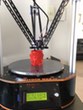
After reading through various review websites that compared printer by printer, I decided to purchase a Rostock MAX V2! Because it is a DIY printer, it is competitively priced while still offering many desirable features. I didn't mind building, as it would allow me to get to know the components and better acclimate myself into this new hobby. Yet, I couldn't just buy a 3D Printer without upgrading it out of the box!

Off to the TrickLaser store I went. After speaking to Brian and the folks over at the store, I was very impressed with overall customer support. Brian was extremely knowledgeable, and was able to honestly tell me what I need or don't need from his website. It is a nice relief when someone isn't pushing a product, but rather pushing honesty and knowledge! He presented the information, the pro's and con's - allowing me to make a choice to purchase said item or not. With that being said, here were the upgrades I went with out of the box:
- Prometheus Metal Hot End
- J-Head Groove Mount for Rostock MAX (E3D bowden with large PTC fitting)
- Carbon Fiber Tube Stand-Offs 36 MM
- Stepper motor insulators (3 pack)
- 300 MM Carbon Fiber Tube Arms for Rostock
- LED Light Ring for Rostock Platform
- LED hot end heating indicator module
- Pen & Tool holder for Rostock MAX
- Wire - 8 conductor 22 gauge (10')

When I initially purchased the Rostock MAX V2, I called in twice and spoke to both JJ and Jason? (ug- just forgot his name while typing this!). Both were extremely nice and helpful people. After my order, they suggested that I checkout this forum. I have been reading a whole bunch, soaking everything up like a sponge. One thing that I read a few times, was that the stock Hot End from the kit would occasional have issues. In speaking with Brian from TrickLaser, he highly suggested the Prometheus - as it would allow me to run just about any filament (other than PLA/ABS) while being extremely reliable with improved print quality. It seems like the various people who have upgraded on the forums are having great experiences as well. Hence - I was compelled to snag the last Prometheus he had in stock. :twisted:

One other topic we discussed was the factory power supply. Brian mentioned that it was adequate, but could be a lot better. A unit with more amperage and a more stable rail under load would provide consistency and make a big difference to the hot plate. I plan on going up to Microcenter and buying cable sleeves, and will look at their power supplies they have for sale for a possible replacement. Anyone have any recommendations?

I plan to start the build on 8/29/15, when all parts get here. Once I get into the build, I will start taking pictures and posting them in this thread.

Thank you,
Mike
ZenOhSix
Printmaster!
Posts: 64
Joined: Tue Aug 25, 2015 6:58 pm

Re: Rostock Max V2 + Upgrades | Build thread

Post by ZenOhSix »

The first two days have been pretty much unpacking, sorting, waiting for upgrade parts to arrive, and painting.

I decided to paint the edges Orange. I used Rustoleum paint, primer, and clear coat. I decided to go with the non-neon Orange color, as it seemed to look better against the black (IMHO). It is the gloss version of Orange.

Here is a quick few pictures of the wood panels and upgrades that came in from TrickLaser:

[img]https://farm1.staticflickr.com/734/2101 ... 8e79_z.jpg[/img]

[img]https://farm6.staticflickr.com/5643/210 ... 03bb_z.jpg[/img]

[img]https://farm6.staticflickr.com/5693/208 ... 2e1f_z.jpg[/img]

[img]https://farm6.staticflickr.com/5706/210 ... 3352_z.jpg[/img]

Also, I decided to upgrade the POWER SUPPLY with an EVGA 500W Bronze unit. In speaking to Brian @ TrickLaser, he mentioned that an upgraded PS that could hold a decent amount of amps would be a nice upgrade to match the Prometheus Hot End. When I was at Microcenter buying some cable management supplies, I decided to pick up this nice PS. It delivers 40 amps on the 12 volt rail. In comparison, the one that came with the kit (450w VIOTEK) puts out only 22 amps. Further, there should be very little voltage drop when powering the heating tray, fans, LEDs, and the Prometheus Hot End. Finally, these power supply is modular - so I only need to plug in the wires I need for the setup, rather than the full rats nest.

[img]https://farm6.staticflickr.com/5706/203 ... 11cf_z.jpg[/img]

Now - it is off to officially start building!

Thanks,
Mike
gchristopher
Printmaster!
Posts: 175
Joined: Mon Dec 08, 2014 2:09 am

Re: Rostock Max V2 + Upgrades | Build thread

Post by gchristopher »

Nice paint job! I also switched to an EVGA PSU, you should be just fine with 40A. (The heated bed is the biggest draw, and it should be around 10A, with the RAMBo rated up to 15A.)

I'd strongly recommend running a larger gauge wire to the heated bed. A lot of people run hotter temperatures for ABS adhesion. Check out teoman's thread, or other links collected when my terminal melted. (Especially telling is the thermal imagery by KAS that shows how the bed wires can be the hottest component in the build.) That, and knowing that the screw terminal connection to the RAMBo is a common point of failure, so get that wire really clean and correctly inserted! I had to rework my RAMBo to replace it with a pluggable connection with a DIY soldered wire plug.

The other easy upgrade that I'd always repeat was to add a sheet of PEI to the print surface. But if you spend a while fussing with glue and hairspray, etc, with different materials first, you'll appreciate the PEI more once you have it?
ZenOhSix
Printmaster!
Posts: 64
Joined: Tue Aug 25, 2015 6:58 pm

Re: Rostock Max V2 + Upgrades | Build thread

Post by ZenOhSix »

gchristopher wrote:Nice paint job! I also switched to an EVGA PSU, you should be just fine with 40A. (The heated bed is the biggest draw, and it should be around 10A, with the RAMBo rated up to 15A.)

I'd strongly recommend running a larger gauge wire to the heated bed. A lot of people run hotter temperatures for ABS adhesion. Check out teoman's thread, or other links collected when my terminal melted. (Especially telling is the thermal imagery by KAS that shows how the bed wires can be the hottest component in the build.) That, and knowing that the screw terminal connection to the RAMBo is a common point of failure, so get that wire really clean and correctly inserted! I had to rework my RAMBo to replace it with a pluggable connection with a DIY soldered wire plug.

The other easy upgrade that I'd always repeat was to add a sheet of PEI to the print surface. But if you spend a while fussing with glue and hairspray, etc, with different materials first, you'll appreciate the PEI more once you have it?
Thank you. Sent you a quick PM. I am trying to create this wiring loom - and need a quick answer:

7 total wires are needed from the Power Supply?

6 Yellow (12v), 7 Black (Ground), 1 Green (Power switch)?

Thanks,
Mike
geneb
ULTIMATE 3D JEDI
Posts: 5358
Joined: Mon Oct 15, 2012 12:47 pm
Location: Graham, WA
Contact:

Re: Rostock Max V2 + Upgrades | Build thread

Post by geneb »

That's kind of a weird way to put it, but yes.

6 Yellow, 6 black for the main compression terminal block.

One black and the green wire for the power switch.

g.
Delta Power!
Defeat the Cartesian Agenda!
http://www.f15sim.com - 80-0007, The only one of its kind.
http://geneb.simpits.org - Technical and Simulator Projects
gchristopher
Printmaster!
Posts: 175
Joined: Mon Dec 08, 2014 2:09 am

Re: Rostock Max V2 + Upgrades | Build thread

Post by gchristopher »

ZenOhSix wrote:Thank you. Sent you a quick PM. I am trying to create this wiring loom - and need a quick answer:

7 total wires are needed from the Power Supply?

6 Yellow (12v), 7 Black (Ground), 1 Green (Power switch)?

Thanks,
Mike
I see Gene already answered, but yes, that wiring is right.

Since my PSU was modular, it was convenient to use 8-pin power extension cables, so I ended up running a couple extra yellow 12v and black ground to the non heat-bed power input terminals on the RAMBo. (pictures)

Most significantly, when my heat bed wiring was melting, the 4 12V wire, 4 ground wire setup to the RAMBo power input was both cool to the touch and registered a solid 12.05V, so the (unnecessarily large 1300W, but on sale) PSU wasn't even working hard to run the printer.

I'm still early in testing, but teoman's recommendation was for 12ga wire. I'll try to come up with some empirical measures the next time I have the printer taken apart. (like measuring resistance at the pads vs at the bullet plugs?) However, my first guess is that with those thick wires, the connector is going to be the most likely point of failure. (The Molex plug I used is rated for 15A, but only 5 connect/disconnect cycles!)
ZenOhSix
Printmaster!
Posts: 64
Joined: Tue Aug 25, 2015 6:58 pm

Re: Rostock Max V2 + Upgrades | Build thread

Post by ZenOhSix »

geneb wrote:That's kind of a weird way to put it, but yes.

6 Yellow, 6 black for the main compression terminal block.

One black and the green wire for the power switch.

g.
Thank you.

So.. I thought I had a modular power supply. When I was shopping with my wife, she swapped the one I had in my hand with one that was $8 cheaper. The one I got was still a very nice unit, but I had to spend the last two hours (with various children distractions) opening it up, cutting the wires out that I didn't need, slicing my finger open, and then buttoning it all back up.

Yep. I have yet to "officially" start building yet, as I had I cleaned up the power supply. I did a quick test with it - all is good.

Here it sits now:

[img]https://farm6.staticflickr.com/5769/210 ... f517_z.jpg[/img]

[img]https://farm6.staticflickr.com/5681/210 ... 6352_z.jpg[/img]

I saved a few extra wires for "future expansion" purposes, else the wires are loomed for the need of the Rostock Max V2 only.

Now, I can officially start putting it together.

Mike
ZenOhSix
Printmaster!
Posts: 64
Joined: Tue Aug 25, 2015 6:58 pm

Re: Rostock Max V2 + Upgrades | Build thread

Post by ZenOhSix »

Ok... Ran into a snag with the manual. The floor is either upside down, or I have some bad parts.

On page 44, figure 4-5 - it shows a picture of how the feet should be installed:

[img]https://farm1.staticflickr.com/709/2083 ... a028_z.jpg[/img]

All peachy... onto page 49. Installing the back plate. Notice figure 4-9:

[img]https://farm1.staticflickr.com/750/2083 ... 2c0d_z.jpg[/img]

Specifically, notice the "TWO TABS PEGS" under the bottom left screw, where the hand is finger tightening the screws in. This is a problem, because the base has the two tab pegs on the RIGHT side of the board (opposite position). This would make it seem like one of two things are wrong:

1) The base board is upside down and I have the feet installed on the wrong side.
2) The rear power supply board is backwards (flipped on the wrong side).

Well, #2 isn't the case because it isn't a symmetrical board. Meaning, if I flip the board over to put the two tab pegs on the RIGHT side of the base board, the holes do not line up anymore. Therefore #1 above must be incorrect.

Going back and looking at it - Page 43 clearly shows which is the "TOP" face. Further, the instructions even have you write "TOP FACE" on it. I ignored that, and specifically looked at the pictures. Which, the picture in figure 4-5 is very misleading. It isn't "WRONG" per-say, as ONE of the THREE leg areas has the FOUR cut notches differently than the other two!

If you put the bottom plate oriented like in figure 4-3:
[img]https://farm6.staticflickr.com/5670/208 ... 24e9_z.jpg[/img]

The bottom cuts where the pegs go does NOT match figure 4-5! Yet, if you rotate the board around, it does. This is very confusing for those who are picture oriented (like me!). Therefore, I would suggest changing picture 4-5 to show one of the OTHER 2 - or make note that 2 are different than the 1.

OR - people can RTFM (I didn't) ! haha

Thanks,
Mike
ZenOhSix
Printmaster!
Posts: 64
Joined: Tue Aug 25, 2015 6:58 pm

Re: Rostock Max V2 + Upgrades | Build thread

Post by ZenOhSix »

Ok.. Checkpoint 1 : COMPLETE

That power supply and my custom wiring job looks darn good in there!

[img]https://farm1.staticflickr.com/678/2102 ... df87_z.jpg[/img]

[img]https://farm1.staticflickr.com/607/2040 ... dba6_z.jpg[/img]

So far, it is pretty straight forward. The manual is very good (if you follow it!). Outside of that one error that I made by the confusing picture (since I am a picture guy), I have had no issues. Ok.. on-wards to the next part.

Thanks,
Mike
geneb
ULTIMATE 3D JEDI
Posts: 5358
Joined: Mon Oct 15, 2012 12:47 pm
Location: Graham, WA
Contact:

Re: Rostock Max V2 + Upgrades | Build thread

Post by geneb »

1. When you've got the power supply pinned between your knees to put screws in, the orientation really doesn't matter. :)

2. Page 6: (in bright yellow)
"Please read this entire guide before you begin assembly of your new Rostock MAX v2! It will help you avoid any unpleasant surprises and will ensure you've got everything you need BEFORE you need it! Understand that the photographs in this assembly guide do NOT tell the whole story of each step! Make sure you read and understand the accompanying text for each step!"

:D

BTW, nice paint job!

g.
Delta Power!
Defeat the Cartesian Agenda!
http://www.f15sim.com - 80-0007, The only one of its kind.
http://geneb.simpits.org - Technical and Simulator Projects
ZenOhSix
Printmaster!
Posts: 64
Joined: Tue Aug 25, 2015 6:58 pm

Re: Rostock Max V2 + Upgrades | Build thread

Post by ZenOhSix »

{... passing the salt to Gene to help him rub it in ...}

:D :D

Ok. Look at this picture:

[img]https://farm1.staticflickr.com/696/2102 ... 41b0_z.jpg[/img]

What do you see? Me making more freaking errors. Oh no - I followed the manual to the "T". The problem is, I forgot I purchased $300.00 in upgrades and went just humming along. Then it hit me; remember those Stepper Motor Sound Isolators I purchased? I then said a few foul words, and then took that pretty picture above.

Going back through and installing them now. :oops:

Thanks,
Mike
ZenOhSix
Printmaster!
Posts: 64
Joined: Tue Aug 25, 2015 6:58 pm

Re: Rostock Max V2 + Upgrades | Build thread

Post by ZenOhSix »

Interesting enough, there are no pictures of the TrickLaser insulator stepper motor installed. Honestly, it is pretty self explanatory - but I like to use pictures as references to ensure I am not doing anything wrong. Anyhow, I took a picture - along with a textual description from Brian (taken from another thread):

[img]https://farm1.staticflickr.com/773/2103 ... 63d7_z.jpg[/img]
Brian from TrickLaser wrote: - Place a steel flat washer then cork washer on each screw.
- Gently tighten the motor screws evenly, just enough to compress cork washers slightly and motor does not wiggle.
- Over tightening can ruin cork washers by splitting them out.
I will also comment that this build is deceiving. I was all excited, as I made it to page 64 and cranking through the bottom base. I was going to wire sleeve the stepper motors, but wanted to read ahead to ensure they didn't need to be cut to length or anything (they don't - but the Extruder does); in doing so, I found myself getting a little discouraged for a quick moment when I realized that my overall completion progress was essentially nil! I knew that I was still early into the entire build, but it just seemed like I was much further along than I really was.

I think it is time to take a break. :)

Thanks,
Mike
geneb
ULTIMATE 3D JEDI
Posts: 5358
Joined: Mon Oct 15, 2012 12:47 pm
Location: Graham, WA
Contact:

Re: Rostock Max V2 + Upgrades | Build thread

Post by geneb »

Well the good news is that the base is the most complex part of the build. :)

Did you remember to offset the belt drive gear the thickness of the cork pad? :)

g.
Delta Power!
Defeat the Cartesian Agenda!
http://www.f15sim.com - 80-0007, The only one of its kind.
http://geneb.simpits.org - Technical and Simulator Projects
ZenOhSix
Printmaster!
Posts: 64
Joined: Tue Aug 25, 2015 6:58 pm

Re: Rostock Max V2 + Upgrades | Build thread

Post by ZenOhSix »

geneb wrote:Well the good news is that the base is the most complex part of the build. :)

Did you remember to offset the belt drive gear the thickness of the cork pad? :)

g.
Seriously - the base is the most complex part? I would have figured it was the easiest, based on what I have seen in the instructions.

Anyhow - thanks for the reminder on the offset belt drive gear, but yes - I did make sure it aligned up accordingly with the new spacing. Here are some pictures of the base completed:

[img]https://farm1.staticflickr.com/671/2041 ... ed22_z.jpg[/img]
-- I think it came out very clean! Taking apart the PSU and getting rid of all those wires sure made it bare in the base!
[img]https://farm6.staticflickr.com/5732/208 ... 5295_z.jpg[/img]

Here is the alignment of the belt drive gear, being offset due to the cork pad insulation:

[img]https://farm6.staticflickr.com/5659/208 ... 560d_z.jpg[/img]

[img]https://farm1.staticflickr.com/658/2103 ... 0d53_z.jpg[/img]

Here is a side view of the Power Supply Unit, after the top has been put on. Check out the 40 AMP load capability!

[img]https://farm1.staticflickr.com/722/2104 ... 07de_z.jpg[/img]

And here is the top panel installed; I like how the lettering turned out. Quite clean!

[img]https://farm1.staticflickr.com/626/2041 ... b9f2_z.jpg[/img]

Well, I sure hope that was the most complex part of the install. I am going to take a break for a few hours, and catch up on some much needed sleep. Any feedback or tips going forward would be much appreciated!

Thank you,
Mike
geneb
ULTIMATE 3D JEDI
Posts: 5358
Joined: Mon Oct 15, 2012 12:47 pm
Location: Graham, WA
Contact:

Re: Rostock Max V2 + Upgrades | Build thread

Post by geneb »

It looks great. I like the wire mesh loom material. Makes it more manageable, that's for sure!

g.
Delta Power!
Defeat the Cartesian Agenda!
http://www.f15sim.com - 80-0007, The only one of its kind.
http://geneb.simpits.org - Technical and Simulator Projects
User avatar
KAS
ULTIMATE 3D JEDI
Posts: 1157
Joined: Thu Dec 04, 2014 6:06 pm

Re: Rostock Max V2 + Upgrades | Build thread

Post by KAS »

Every time I see these build threads, I keep kicking myself in the ass for not painting the edges.

Great job, love the color scheme.
User avatar
teoman
ULTIMATE 3D JEDI
Posts: 1770
Joined: Sat May 24, 2014 5:43 pm

Re: Rostock Max V2 + Upgrades | Build thread

Post by teoman »

Yeah mee too!

And so many little things i would have done differently or upgraded a little bit.

Should sell the printer for a little profit and start over just because the build was so much fun.
When on mobile I am brief and may be perceived as an arsl.
3D-Print
Printmaster!
Posts: 519
Joined: Mon Jan 05, 2015 9:39 pm
Location: Omaha, Nebraska

Re: Rostock Max V2 + Upgrades | Build thread

Post by 3D-Print »

Agree awesome job. Love the color and detail.
My 3D-Printing learning curve is asymptotic to a Delta's X, Y and Z-axes
ZenOhSix
Printmaster!
Posts: 64
Joined: Tue Aug 25, 2015 6:58 pm

Re: Rostock Max V2 + Upgrades | Build thread

Post by ZenOhSix »

What is the general opinion of the Simplify 3D software?

It looks like it has parameter support for the Rostock Max v2 - and it has some neat features. I don't mind paying $150 if it will save time, filament, and make my prints better.

Thanks,
Mike
ZenOhSix
Printmaster!
Posts: 64
Joined: Tue Aug 25, 2015 6:58 pm

Re: Rostock Max V2 + Upgrades | Build thread

Post by ZenOhSix »

I resumed the build today, albeit later in the day than I wanted to. For some reason, I couldn't will myself to get up and begin. Yet, when I did - I found something that put a frown on my face. As I resumed on page 69 - Installing the Onyx Heated Bed - I unpacked the bed and components, only to find a chip in the Onyx Heated Bed:

[img]https://farm1.staticflickr.com/730/2044 ... 57cf_z.jpg[/img]

[img]https://farm6.staticflickr.com/5640/204 ... c0e8_z.jpg[/img]

I am not sure if it occurred in shipping or it was dropped at the factory, but the chip goes 1/2 way into the layered bed. I called SeeMyCNC and spoke to JJ. He recommended that I put some Kapton tape over it, to prevent a possible shorting if anything metal were to make contact. I think what I will do instead is mark it up with some black marker and then put some CA Glue over it, filling the void. Never-the-less, it drives me nuts going through all this work to make this thing look pretty, and I find a chip! It is like buying a new car with that fresh shiny paint - only to see a big chip on the hood. :evil: :( :x

Off to go build..

Mike
User avatar
bvandiepenbos
Printmaster!
Posts: 923
Joined: Thu Apr 05, 2012 11:25 pm
Location: Goshen, IN
Contact:

Re: Rostock Max V2 + Upgrades | Build thread

Post by bvandiepenbos »

Great looking build.
Nice work.

by the way, you CAN print PLA and ABS with the Prometheus. ( I think you miss typed in your first post, but just making sure)
~*Brian V.

RostockMAX v2 (Stock)
MAX METAL "ShortyMAX"
MAX METAL Rostock MAX Printer Frame
NEMESIS Air Delta v1 & v2 -Aluminum delta printers
Rostock MAX "KITT" - Tri-Force Frame
GRABER i3 "Slim"
ZenOhSix
Printmaster!
Posts: 64
Joined: Tue Aug 25, 2015 6:58 pm

Re: Rostock Max V2 + Upgrades | Build thread

Post by ZenOhSix »

Break time for dinner!

I haven't completed much today, thus far. I have been working slow, taking my time. At this point, I have the Onyx bed mounted. In doing so, I soldered the wires to the bed as the manual indicated as well as RTVing the thermo on. I took this opportunity to put wire sleeves on, matching everything I have done thus far.

[img]https://farm6.staticflickr.com/5777/208 ... edbf_z.jpg[/img]

[img]https://farm6.staticflickr.com/5682/210 ... 18fe_z.jpg[/img]

[img]https://farm6.staticflickr.com/5833/210 ... 891e_z.jpg[/img]

Per the recommendation of gchristopher and the other threads, I took the opportunity to run larger sized wiring to power the Onyx bed. I had some 12 gauge noodle wire left over, from my RC collection. I only had 10" of black wire, but lots of red. Therefore, underside the Onyx I started with the RED colored wire but soldered it to the black colored; when wiring to the controller, no one would ever know! :mrgreen:

[img]https://farm1.staticflickr.com/718/2088 ... a159_z.jpg[/img]

[img]https://farm1.staticflickr.com/751/2107 ... 6a9d_z.jpg[/img]

Because I used larger wires, I had to drill the hole going into the base a little larger to fit the 12 gauge AND the wiring sleeves. It cleaned up well, using a black permanent marker to clean up the rough edges. After that, everything bolted down as expected.

[img]https://farm1.staticflickr.com/710/2044 ... f325_z.jpg[/img]

After dinner, I think I am supposed to start on the towers next.

Thanks,
Mike
ZenOhSix
Printmaster!
Posts: 64
Joined: Tue Aug 25, 2015 6:58 pm

Re: Rostock Max V2 + Upgrades | Build thread

Post by ZenOhSix »

bvandiepenbos wrote:Great looking build.
Nice work.

by the way, you CAN print PLA and ABS with the Prometheus. ( I think you miss typed in your first post, but just making sure)
Ha! Yep - a type-o. I will go back and fix it. Thanks for the note and compliment.

Thanks,
Mike
User avatar
crocky
Printmaster!
Posts: 269
Joined: Tue Aug 12, 2014 6:55 pm
Location: Werribee, Aust

Re: Rostock Max V2 + Upgrades | Build thread

Post by crocky »

Nice paint job :)

Simplify 3D is pretty good, takes a little adjusting and then you will like it.
Bob
Rostock Max V2, Ball Cup Arms, New Carriages, HE280, Dampers, PSU Breathing, Simplify 3D, GeckoTek3D, Raspberry Pi3. Duet soon... Kossel Mini still under construction.
Delta's are the way!
ZenOhSix
Printmaster!
Posts: 64
Joined: Tue Aug 25, 2015 6:58 pm

Re: Rostock Max V2 + Upgrades | Build thread

Post by ZenOhSix »

crocky wrote:Nice paint job :)

Simplify 3D is pretty good, takes a little adjusting and then you will like it.
Thanks! I like Orange, and the black/orange contrasts well.

In regards to Simplify 3D - I have never used any CAD or SLICER program before. Therefore, I would be learning on that. Hopefully, there won't be any new "getting use to" since I have no previous experience.

Is that what you mean? Or did you mean that the Rostock required additional adjustments to use Simplify 3D?

Thank you,
Mike
Post Reply

Return to “The Build Zone”