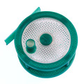
I'd like to level the print bed using a dial caliper/indicator. The dial has a .001 mm accuracy.
http://www.harborfreight.com/1-inch-sae ... 93295.html
http://shop.seemecnc.com/Rostock-Pen-To ... egoryId=-1
Repetier has a button called "Dry Run". Is it possible to run the print without heating the extruder and also without using up the filament?
The dial gauge is in the position where the extruder normally is.
I'm trying to run Onyx_Bed_Level_Aid.stl to fine tune the bed.
Leveling print bed using dial caliper
-
Polygonhell
- ULTIMATE 3D JEDI
- Posts: 2417
- Joined: Mon Mar 26, 2012 1:44 pm
- Location: Redmond WA
Re: Leveling print bed using dial caliper
If you write GCode that doesn't try and set the temperature or extrude anything, then you shouldn't have any issues.jesse wrote:I'd like to level the print bed using a dial caliper/indicator. The dial has a .001 mm accuracy.
http://www.harborfreight.com/1-inch-sae ... 93295.html
http://shop.seemecnc.com/Rostock-Pen-To ... egoryId=-1
Repetier has a button called "Dry Run". Is it possible to run the print without heating the extruder and also without using up the filament?
The dial gauge is in the position where the extruder normally is.
I'm trying to run Onyx_Bed_Level_Aid.stl to fine tune the bed.
I believe Dry Run filters these out in repetier host, but I haven'y used it.
Printer blog http://3dprinterhell.blogspot.com/
Re: Leveling print bed using dial caliper
You should probably level your bed at temperature. My bed warps .5mm at 80deg in the middle. A glass build plate may minimize this but the warping might also be why my glass plate split. Check it cold and hot.
Sublime Layers - my blog on Musings and Experiments in 3D Printing Technology and Art
Start Here:
A Strategy for Successful (and Great) Prints
Strategies for Resolving Print Artifacts
The Eclectic Angler
Re: Leveling print bed using dial caliper
Thanks for the replies. The solution I ended up using was to remove the filament. The printer has no idea and everything still works like normal.
Re: Leveling print bed using dial caliper
@mhackney: Was your old glass also an borosilicate, heat resistent one?
Re: Leveling print bed using dial caliper
No, my original glass was 3/16" normal window glass. The drawing is on my build thread - I had it custom cut into a circle with a flat area cut off for the electronics on the gen 2 Onyx. I've been using 1/8" window glass on my H-1 for over a year at these temperatures. I thought the larger build plate would benefit from a little extra thickness to resist breakage! I think one of 2 things happened - either the glass was too thick to dissipate stress from the heating or it broke from mechanical stress from the Onyx warping at high temperature. I am actually leaning towards the first based on the fracture shape. Of course a combination or other reasons are possible!
Sublime Layers - my blog on Musings and Experiments in 3D Printing Technology and Art
Start Here:
A Strategy for Successful (and Great) Prints
Strategies for Resolving Print Artifacts
The Eclectic Angler

Re: Leveling print bed using dial caliper
Are you using Repetier firmware?
When you calibrate are you changing mechanically IE the screws, or are you doing it in the EEPROM? I'm unclear as to which method I should be using.
When you calibrate are you changing mechanically IE the screws, or are you doing it in the EEPROM? I'm unclear as to which method I should be using.
Re: Leveling print bed using dial caliper
I am using Repetier firmware. Here's how I did it:
1) Install your build surface (glass plate, etc) and make sure the heated bed is up to temperature. I print ABS at 100°C bed, so that's what I used. The Onyx warps as it heats up so unless you have a flat surface on top of it, you will not be able to get a planar surface to calibrate to. If you are printing on tape on the Onyx, do the following steps cold and deal with the warping issue depending on the location of your print, etc.
2) Calibrate Z at 0,0,0 in firmware. These are listed as the following in the firmware:
#define X_MAX_LENGTH 369.0
#define Y_MAX_LENGTH 369.0
#define Z_MAX_LENGTH 369.0
Here's how I did it: I set these to 375 so they are longer than my actual travel. Then I homed and brought the nozzle down to z=20mm (G0 Z20 F2000). From there I used the buttons in Repetier host to slowly lower the nozzle (decrease Z) to the build surface. Start with the 10mm and then 1 and finally .1mm for fine adjustment. I used a piece of cigarette paper between the bed and nozzle (make sure your nozzle is clean!) to test the "fit" you can use a .001" (or metric equivalent) feeler gauge too. You want to bring the nozzle down until it just "snags" the paper or gauge. At this point, read the Z height on the Z axis display in Repetier Host. Subtract this number from 375mm to get your actual max lengths. So, for me this measurement was exactly 6.0mm, so 375.0mm - 6.0mm = 369.0mm. If you are using EEPROM settings, you can simply change this in the EEPROM without needing to recompile and upload your firmware. That makes it a lot faster to do and test. Check this at least 3 times to make sure it is reproducible using this process:
Home All - move to G0 Z10 - use buttons to lower 1mm nine times - place gauge - lower by .1mm 10 times - nozzle should just graze gauge
3) now with your Z = 0 set you can adjust the planarity of the bed using the homing switches at the towers. This is done one tower at a time with the nozzle positioned as close to the tower as reasonable. The process is described in the manual but use the "true" circumference points. These are:
X: G0 X-77.94 Y-45 F2000
Y: G0 X77.94 Y-45 F2000
Z: G0 X0 Y90 F2000
(note F2000 is feed rate) These locations came from http://minow.blogspot.com (a MUST read for calibrating!)
At each one of these locations, you move down (using the Z buttons) until you get to Z=0. If you are lucky, the gauge will just graze the nozzle and you are done at that tower. If not, the nozzle will either be above the bed (case A) or the display will show that Z has not been reached (case B).
In case A, you can measure the gap and set the stop screw at the top of the tower (see a few lines below).
In case B, write down the extra distance the Z could go and set the stop screw as below.
Setting the stop screw: These screws are 6-32. That means they will advance .03125" per revolution. Converted to metric that is 0.79mm per revolution.
case A - let's say that you measured a gap of .4mm. This means that the firmware thinks the tower length is .4mm shorter than it actually is! So, you need to "raise" the stop screw (lefty-loosey or counter clockwise looking from the top) .4mm - which is about 1/2 of a turn.
case B - let's say that Repetier host shows (Z axis display) that you still have .2mm to go before reaching Z=0. This means the firmware thinks the tower length is .2mm longer than it actually is, so you need to "lower" the stop screw .2mm or about 1/8 of a turn, in this case righty-thighty or screw clockwise from the top.
That's it! Now you should go back and recheck everything 1 or 2 times to be sure.
Note that there is an advanced planarity adjustment described in the link above. I have not done this yet since my glass plate broke and I'm waiting for the replacement. If your machine is really "off" the re-check step above will show that Z=0 at X=Y=0 will not be correct. I'd adjust one more time through the entire process and if you still have this problem, then do the planarity adjustment. Hopefully I'll be there by Tuesday or Wednesday when my plate arrives!
There is an "auto calibrate" mode/command in the LCD controller firmware in Repetier. I have not had a chance to investigate it. In theory, all of the above could be accomplished in soft settings with the right math. It probably does not hurt to try to calibrate mechanically first though!
DISCLAIMER: there is some probability that there are mistakes or better ways to do the above. This is my first delta printer and I'm only a few weeks in and don't have a lot of experience yet!
Sublime Layers - my blog on Musings and Experiments in 3D Printing Technology and Art
Start Here:
A Strategy for Successful (and Great) Prints
Strategies for Resolving Print Artifacts
The Eclectic Angler
Re: Leveling print bed using dial caliper
Thanks for the detailed description. I found myself going in circles as far as the screw adjustments - adjusting one would throw off others. I eventually got it done but it took a lot more than 1-2 passes. Anyone else experience this, or is my machine just messing with my head?
-
Polygonhell
- ULTIMATE 3D JEDI
- Posts: 2417
- Joined: Mon Mar 26, 2012 1:44 pm
- Location: Redmond WA
Re: Leveling print bed using dial caliper
The secret if there is one is to nominate one tower as a master, and just adjust the other two.theverant wrote:Thanks for the detailed description. I found myself going in circles as far as the screw adjustments - adjusting one would throw off others. I eventually got it done but it took a lot more than 1-2 passes. Anyone else experience this, or is my machine just messing with my head?
All you're trying to do is get 3 points in a horizontal plane.
Once you've done that, you can measure the center and set the DELTA_RADIUS, and finally measure and set the Z_MAX_LENGTH
Printer blog http://3dprinterhell.blogspot.com/
Re: Leveling print bed using dial caliper
Polygonhell, I don't quite understand that how that works in practice. Basically, if the nozzle stops all three towers by say 1mm, 2 mm and 3mm above the bed and I have Z=0 set for at X=Y=0, don't you have to adjust all 3 stop screws? Perhaps I am not understanding how you calibrate.
Cheers,
Michael
Cheers,
Michael
Sublime Layers - my blog on Musings and Experiments in 3D Printing Technology and Art
Start Here:
A Strategy for Successful (and Great) Prints
Strategies for Resolving Print Artifacts
The Eclectic Angler
-
Polygonhell
- ULTIMATE 3D JEDI
- Posts: 2417
- Joined: Mon Mar 26, 2012 1:44 pm
- Location: Redmond WA
Re: Leveling print bed using dial caliper
You don't have to get them all to 0 just the same value.mhackney wrote:Polygonhell, I don't quite understand that how that works in practice. Basically, if the nozzle stops all three towers by say 1mm, 2 mm and 3mm above the bed and I have Z=0 set for at X=Y=0, don't you have to adjust all 3 stop screws? Perhaps I am not understanding how you calibrate.
Cheers,
Michael
Pick one, adjust the other two, once adjusted, measure 0,0 and adjust DELTA_RADIUS to make all 4 points the same.
THEN adjust the final ZHeight.
The mistake is to try and work off 0,0 as some correct 0 value, it will change with every adjustment.
Printer blog http://3dprinterhell.blogspot.com/
Re: Leveling print bed using dial caliper
I knew there was a piece to the puzzle missing.Polygonhell wrote:The secret if there is one is to nominate one tower as a master, and just adjust the other two.
All you're trying to do is get 3 points in a horizontal plane.
Once you've done that, you can measure the center and set the DELTA_RADIUS, and finally measure and set the Z_MAX_LENGTH
Re: Leveling print bed using dial caliper
Thanks Polygonhell. I'll try this when I recalibrate when my glass arrives. Are you simply setting the n_MAX_LENGTH values in the firmware or physically setting the stop screw? And I presume you are measuring the nozzle height with feelers to determine the height of the nominated tower.
I have to say though - and I might just be lucky - that I've calibrated 4 times now using the previously posted process and it worked great on the first cycle through. No additional adjustments were needed not did I have to mess with DELTA_RADIUS.
Have you looked at and/or used the calibration code in the Repetier firmware?
cheers,
Michael
Sublime Layers - my blog on Musings and Experiments in 3D Printing Technology and Art
Start Here:
A Strategy for Successful (and Great) Prints
Strategies for Resolving Print Artifacts
The Eclectic Angler
Re: Leveling print bed using dial caliper
FYI, it's not local which is always a plus... but here's another caliper with the same accuracy for cheap that'll measure up to 6" instead of 1". And it's really cheap! http://www.amazon.com/gp/product/B0019O ... UTF8&psc=1. I ordered one Friday should be here tomorrowjesse wrote:I'd like to level the print bed using a dial caliper/indicator. The dial has a .001 mm accuracy.
http://www.harborfreight.com/1-inch-sae ... 93295.html
http://shop.seemecnc.com/Rostock-Pen-To ... egoryId=-1
Repetier has a button called "Dry Run". Is it possible to run the print without heating the extruder and also without using up the filament?
The dial gauge is in the position where the extruder normally is.
I'm trying to run Onyx_Bed_Level_Aid.stl to fine tune the bed.
DIY instructions/videos/hardware links:
Carbon fiber rods w/ ball joints for Rostock MAX ~$40 http://forum.seemecnc.com/viewtopic.php?f=36&t=2165
Carbon fiber rods w/ ball joints for Rostock MAX ~$40 http://forum.seemecnc.com/viewtopic.php?f=36&t=2165
Re: Leveling print bed using dial caliper
That looks like the one I bought labelled as a Mastercraft at Candiantire. Very useful and you can switch the reading between inches and mmstexsc98 wrote:FYI, it's not local which is always a plus... but here's another caliper with the same accuracy for cheap that'll measure up to 6" instead of 1". And it's really cheap! http://www.amazon.com/gp/product/B0019O ... UTF8&psc=1. I ordered one Friday should be here tomorrow
Re: Leveling print bed using dial caliper
So I have my three triangle points corrected, but the centre is slightly high @ 0.1mm how do we adjust the DELTA_RADIUS to correct this? I assume that's what you meant by using that value. This is done in the firmware, or is there a way to adjust it in the EEPROM?Polygonhell wrote:You don't have to get them all to 0 just the same value.
Pick one, adjust the other two, once adjusted, measure 0,0 and adjust DELTA_RADIUS to make all 4 points the same.
THEN adjust the final ZHeight.
The mistake is to try and work off 0,0 as some correct 0 value, it will change with every adjustment.
Thanks!
-
Polygonhell
- ULTIMATE 3D JEDI
- Posts: 2417
- Joined: Mon Mar 26, 2012 1:44 pm
- Location: Redmond WA
Re: Leveling print bed using dial caliper
I adjust the screws to get the 3 the same and in the final step set the Z_MAX_LENGTH in the firmware or in my case the EEPROM.mhackney wrote:Thanks Polygonhell. I'll try this when I recalibrate when my glass arrives. Are you simply setting the n_MAX_LENGTH values in the firmware or physically setting the stop screw? And I presume you are measuring the nozzle height with feelers to determine the height of the nominated tower.
I have to say though - and I might just be lucky - that I've calibrated 4 times now using the previously posted process and it worked great on the first cycle through. No additional adjustments were needed not did I have to mess with DELTA_RADIUS.
Have you looked at and/or used the calibration code in the Repetier firmware?
cheers,
Michael
I'd you're using my copy of Repetier you have my DELTA_RADIUS adjustment, mine was close but not perfect.
I need to look at the calibration code in Repetier, theoretically it's simple enough to calculate a flat plane given any 3 measurements on the bed.
Printer blog http://3dprinterhell.blogspot.com/
-
Polygonhell
- ULTIMATE 3D JEDI
- Posts: 2417
- Joined: Mon Mar 26, 2012 1:44 pm
- Location: Redmond WA
Re: Leveling print bed using dial caliper
That one has to be done in the firmware, the link MHackney posted tells you how to adjust it, what I ended up doing was to adjust it by 1mm and see what effect it had, then use that to calculate the change I wanted, took me 2 or 3 iterations to get it close enough.theverant wrote:So I have my three triangle points corrected, but the centre is slightly high @ 0.1mm how do we adjust the DELTA_RADIUS to correct this? I assume that's what you meant by using that value. This is done in the firmware, or is there a way to adjust it in the EEPROM?Polygonhell wrote:You don't have to get them all to 0 just the same value.
Pick one, adjust the other two, once adjusted, measure 0,0 and adjust DELTA_RADIUS to make all 4 points the same.
THEN adjust the final ZHeight.
The mistake is to try and work off 0,0 as some correct 0 value, it will change with every adjustment.
Thanks!
You'll never get everything perfect because the endstops aren't perfect, but you should aim for 0.05mm or better.
Printer blog http://3dprinterhell.blogspot.com/