Mhackney's Rostock Max
Re: Mhackney's Rostock Max
Good idea, I can do that. I've been banging on this termistor config issue with no luck. I have checked the RAMBo pin out assignments and schematic against my .80 configuration and the new .91 and can't find a thing wrong! Yet it won't read temps. As soon as I upload my .80 firmware, temps read just fine. Something I'm missing...
Sublime Layers - my blog on Musings and Experiments in 3D Printing Technology and Art
Start Here:
A Strategy for Successful (and Great) Prints
Strategies for Resolving Print Artifacts
The Eclectic Angler
Re: Mhackney's Rostock Max
Very cool to hear that FEATURE_CONTROLLER 13 is working for you! That was the patch I have submitted.
You should not need to change anything in pins.h. The only thing you should have to touch is Configuration.h.
Do you have the correct thermistor type and settings?
Can you attach your Configuration.h files from the .80 version and your .91 version?
You should not need to change anything in pins.h. The only thing you should have to touch is Configuration.h.
Do you have the correct thermistor type and settings?
Can you attach your Configuration.h files from the .80 version and your .91 version?
-
Eaglezsoar

- ULTIMATE 3D JEDI
- Posts: 7159
- Joined: Sun Apr 01, 2012 5:26 pm
Re: Mhackney's Rostock Max
Maybe step away, get a cup of coffee and come back to it after you take a break, you always figure these things out I think you just need a break to clear your mind.mhackney wrote:Good idea, I can do that. I've been banging on this termistor config issue with no luck. I have checked the RAMBo pin out assignments and schematic against my .80 configuration and the new .91 and can't find a thing wrong! Yet it won't read temps. As soon as I upload my .80 firmware, temps read just fine. Something I'm missing...
This is one of the reasons very few have attempted the upgrade, too many reports of failure but I know you refuse to fail.
“ Do Not Regret Growing Older. It is a Privilege Denied to Many. ”
Re: Mhackney's Rostock Max
Have you seen this video? -->Eaglezsoar wrote:If you had the timeperhaps you could write a blurb on how a new user could upgrade to .91
Don't hit me with a thrown object it was just a suggestion. No one has done this yet.
http://www.youtube.com/watch?v=A4yMV18oMbw
-
Eaglezsoar
- ULTIMATE 3D JEDI
- Posts: 7159
- Joined: Sun Apr 01, 2012 5:26 pm
Re: Mhackney's Rostock Max
The video is 8 months old and covers the basics, it's not going to cover the nuances of .91int2str wrote:Have you seen this video? -->Eaglezsoar wrote:If you had the time
Don't hit me with a thrown object it was just a suggestion. No one has done this yet.
http://www.youtube.com/watch?v=A4yMV18oMbw
There are snippets of information all over the forum but no one has created a compilation of all the steps necessary.
Most of it is straight forward but things like the code you had them imbed and other gotchas exist that the usual user
doesn't know about. Because they don't know enough to download a copy of firmware from SeeMeCNC and look at
the configuration.h they have no idea what to plug in for the thermistors, steps per mm, etc. The video helps but is
not enough to upgrade to .91 I have to look at it from the newbies viewpoint because they are the ones I deal with
on a daily basis.
“ Do Not Regret Growing Older. It is a Privilege Denied to Many. ”
Re: Mhackney's Rostock Max
Ok, it turns out that in my .80 Configuration.h I had thermistor type set to 97 for both bed and hot end - using a generic thermistor table. I don't recall why I did that but oddly, this firmware worked fine. I am using the same Arduino IDE (1.0.3) to compile both .80 and .91 so I would expect the thermistor tables to be the same so if it worked in .80 it should work in .91. When I set the thermister type to 1, now I am getting thermistor readings but I have to check with my temp probe to make sure I am getting accurate readings.
Time to try some prints.
Time to try some prints.
Sublime Layers - my blog on Musings and Experiments in 3D Printing Technology and Art
Start Here:
A Strategy for Successful (and Great) Prints
Strategies for Resolving Print Artifacts
The Eclectic Angler
Re: Mhackney's Rostock Max
Actually, I had modified my pins.h last year - I blew the thermistor port for the heated bed thermistor and remapped it to pin 7. I haven't got around to change it now that I have a 100% functioning replacement RAMBo. But, as you saw in my last post, the thermistor type did turn out to be wrong. Why it worked with .80 and not .91 is a mystery though!int2str wrote:Very cool to hear that FEATURE_CONTROLLER 13 is working for you! That was the patch I have submitted.
You should not need to change anything in pins.h. The only thing you should have to touch is Configuration.h.
Do you have the correct thermistor type and settings?
Can you attach your Configuration.h files from the .80 version and your .91 version?
Sublime Layers - my blog on Musings and Experiments in 3D Printing Technology and Art
Start Here:
A Strategy for Successful (and Great) Prints
Strategies for Resolving Print Artifacts
The Eclectic Angler
Re: Mhackney's Rostock Max
Ok, I have things working but unfortunately my bed height/curvature calibration is off. I verified that switching back to .80 firmware, it is dead nuts on, perfectly flat across the plate and the Z height is perfect to get a good first layer. There are a number of new settings for delta printers in the .91 firmware and I tried to carry everything over as best I could. But, now it seems things are off. I didn't check everything yet, I simply reset the Z height - it was 2.6mm shorter than with the .80 firmware - and now trying a small print. I can see that the first layer is very thin in the +X direction and about right in the -X. Can't tell on the Y (it's a Mr. Jaws - long and skinny).
So, anyhow, has anyone here done anything with the auto bed leveling in .91 or made a probe?
cheers,
Michael
So, anyhow, has anyone here done anything with the auto bed leveling in .91 or made a probe?
cheers,
Michael
Sublime Layers - my blog on Musings and Experiments in 3D Printing Technology and Art
Start Here:
A Strategy for Successful (and Great) Prints
Strategies for Resolving Print Artifacts
The Eclectic Angler
-
Eaglezsoar
- ULTIMATE 3D JEDI
- Posts: 7159
- Joined: Sun Apr 01, 2012 5:26 pm
Re: Mhackney's Rostock Max
626pilot made a probe here http://www.thingiverse.com/thing:161753mhackney wrote:Ok, I have things working but unfortunately my bed height/curvature calibration is off. I verified that switching back to .80 firmware, it is dead nuts on, perfectly flat across the plate and the Z height is perfect to get a good first layer. There are a number of new settings for delta printers in the .91 firmware and I tried to carry everything over as best I could. But, now it seems things are off. I didn't check everything yet, I simply reset the Z height - it was 2.6mm shorter than with the .80 firmware - and now trying a small print. I can see that the first layer is very thin in the +X direction and about right in the -X. Can't tell on the Y (it's a Mr. Jaws - long and skinny).
So, anyhow, has anyone here done anything with the auto bed leveling in .91 or made a probe?
cheers,
Michael
Discussion here: http://forum.seemecnc.com/viewtopic.php ... 1&start=10
No one appears to have an actual working model.
“ Do Not Regret Growing Older. It is a Privilege Denied to Many. ”
-
Eaglezsoar
- ULTIMATE 3D JEDI
- Posts: 7159
- Joined: Sun Apr 01, 2012 5:26 pm
Re: Mhackney's Rostock Max
SeeMeCNC designed another probe here: http://forum.seemecnc.com/viewtopic.php?f=54&t=2445
I don't believe it went beyond the design stage.
I don't believe it went beyond the design stage.
“ Do Not Regret Growing Older. It is a Privilege Denied to Many. ”
Re: Mhackney's Rostock Max
[img]http://mhackney.zenfolio.com/img/s10/v1 ... 0427-4.jpg[/img]
Yeah, I think I nailed the calibration on this one! it is dead flat and this bed level aid printed perfectly. Even thickness over the entire thing. And I was able to remove it from the bed in one piece too.
cheers,
Michael
Yeah, I think I nailed the calibration on this one! it is dead flat and this bed level aid printed perfectly. Even thickness over the entire thing. And I was able to remove it from the bed in one piece too.
cheers,
Michael
Sublime Layers - my blog on Musings and Experiments in 3D Printing Technology and Art
Start Here:
A Strategy for Successful (and Great) Prints
Strategies for Resolving Print Artifacts
The Eclectic Angler
Re: Mhackney's Rostock Max
So you just did regular calibration or auto bed leveling?
Re: Mhackney's Rostock Max
Manual calibration soup to nuts.
Sublime Layers - my blog on Musings and Experiments in 3D Printing Technology and Art
Start Here:
A Strategy for Successful (and Great) Prints
Strategies for Resolving Print Artifacts
The Eclectic Angler
Re: Mhackney's Rostock Max
That's what I'm going for when i get this mic 6 cut
Re: Mhackney's Rostock Max
You'll have a née flat build surface, that's for sure. The Onyx warps like crazy when it heats up. Even clips on the borosilicate are marginally effective.
Sublime Layers - my blog on Musings and Experiments in 3D Printing Technology and Art
Start Here:
A Strategy for Successful (and Great) Prints
Strategies for Resolving Print Artifacts
The Eclectic Angler
Magnetic Arm lay up
I have all the hardware and materials I need to complete my magnetic arm upgrade. I thought about turning Delrin rod ends but my printer is working so well right now and Xnaron's design is so nice, I decided to print these. The only critical dimension (other than IDs of course) is the gap between the bearing and magnet. Setting up my lathe and tooling to do this would be time consuming. By printing them, I get a batch of 12 going and come back when they're done!
After the ends were printed, I lapped the hemispherical recess with a bearing and jeweler's rouge and oil at low speed on my lathe. The idea is to polish the surface, not melt it! (ask me how I found that out). Once lapped, they are very smooth as the video will show. 3D printing is a great way to make these ends.
Here is a photo of lapping the end:
[img]http://mhackney.zenfolio.com/img/s9/v91 ... 9856-3.jpg[/img]
and here's one of the dry assembly:
[img]http://mhackney.zenfolio.com/img/s5/v12 ... 5583-3.jpg[/img]
The "stud" is a 6-32 screw. I have 6-32 threaded steel rod to use for the final product. I went with 6-32 over the 3mm others are using for their "glued cap screws" for the simple reason that 6-32 taps are pretty robust. I do a lot of tapping in 1, 2 and 3mm and 2-56, 4-40 etc and know that tapping hard materials with small taps is a pain. I also overboard the tap hole a bit so the threads are shallower. That should not be a problem for this application. Normally you would use a #36 gauge drill, I used a #31.
Here is a video showing how smooth they are:
[youtube]http://www.youtube.com/watch?feature=pl ... MuPkk3LEsE[/youtube]
hmm, I guess embedded videos don't work here. Here's the link to the video on my YouTube channel:
http://www.youtube.com/watch?feature=pl ... MuPkk3LEsE
I am very happy with how this is turning out.
cheers,
Michael
Sublime Layers - my blog on Musings and Experiments in 3D Printing Technology and Art
Start Here:
A Strategy for Successful (and Great) Prints
Strategies for Resolving Print Artifacts
The Eclectic Angler
Re: Mhackney's Rostock Max
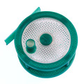
The magnet on this end piece releases at just a hair over 2 pounds - something like 2lbs 1 oz in three trials. Not bad! That gives me 4 lbs at each pair of rod ends. Should be able to hold the Kraken!
Sublime Layers - my blog on Musings and Experiments in 3D Printing Technology and Art
Start Here:
A Strategy for Successful (and Great) Prints
Strategies for Resolving Print Artifacts
The Eclectic Angler

Re: Mhackney's Rostock Max
Michael, I've been working out a similar design but everybody I talk to discourages me from trying to drill and tap a 1/2" ball bearing. I've been spending lots of time at NextFab learning how to use the mill and lathe, but I haven't tried this yet.
What are your bearings made of? Did you anneal them before drilling and tapping?
- dan
What are your bearings made of? Did you anneal them before drilling and tapping?
- dan
Re: Mhackney's Rostock Max
BTW, I've made my own delrin rod ends on the Bridgeport using a half inch ball end mill for the socket and a 3/8" square end mill for the magnet. Haven't decided on Al vs. carbon fiber for the rods. Did you make your rods adjustable to tweak the length?
- dan
- dan
Re: Mhackney's Rostock Max
Dan, there is no problem with drilling and tapping these, you just have to have the right tools. I used a 3/8" 5C collet in a collet chuck on my lathe. I fabricated a spacer in Delrin to position the bearing in the right spot so it is clamped at its periphery. Then, I spot drilled and drilled on the first one. But, I have a short carbide drill (#31) to drill without spotting. Then, use a new, sharp 6-32 tap with tapping fluid and a T- handle tap wrench with a centering pin in the lathe tailstock. The entire "trick' is to make sure the bearing is clamped firmly and there tap wrench is perfectly in line with the hole with no wobbles. It really was not difficult to drill and tap.
They are nickel plated steel balls I got from K&J Magnetics where I got the mangers. Do not anneal the bearings, that is sure to distort them and it is not needed.
Sounds like you are using larger bearings (1/2") so you could even go up to an 8-32 screw - even easier to drill and tap without breakage. Make sure to stop short, you don't want to go through the bearing and you only need a few threads to hold securely. I went about 3/4 of the way into the bearing and use a plug tap to tap closer to the bottom.
I did not want or need the complexity of adjustable rods. I built a jig that holds the ball ends at the right location and simply epoxy the end pieces onto the tube. I actually epoxy one end to the rods first and let it cure so I can focus on one end. The tube is a few mm shorter than required to give a little wiggle room in the jig. Once the epoxy cures, the rods are all the perfect and correct length "ball to ball". Xnarnon has STLs for the jig in his sources. I wanted a jig to make 6 at a time so I machined it special to make this easy. I'm thinking about offering kits or parts.
cheers,
Michael
Sublime Layers - my blog on Musings and Experiments in 3D Printing Technology and Art
Start Here:
A Strategy for Successful (and Great) Prints
Strategies for Resolving Print Artifacts
The Eclectic Angler
Re: Mhackney's Rostock Max
Here's a little "forest" of perfectly printed ends:
[img]http://mhackney.zenfolio.com/img/s10/v1 ... 8000-3.jpg[/img]
The book Hackers has a great quote referring to the early computer & software hackers (who were really early "Makers") that goes like "tools to make tools" - referring to programmers creating programs to make programming easier! RepRap and 3D printing at the hobbyest level is exactly that "tools to make tools"!
cheers,
Michael
Sublime Layers - my blog on Musings and Experiments in 3D Printing Technology and Art
Start Here:
A Strategy for Successful (and Great) Prints
Strategies for Resolving Print Artifacts
The Eclectic Angler
Re: Mhackney's Rostock Max
Right, I'm using 1/2" balls, but I got bearing-quality E52100 alloy steel hardened balls from McMaster-Carr, so maybe they're too hard. I was planning on using JB Weld to glue them to hex cap screws I've milled cups in, but I've been stalling on that while I figure out how to machine the platform out of aluminum. I was also considering just milling the cups in the platform itself, but I think differential thermal expansion would be a problem.
I think I've got what you did with the delrin spacer. Do you mind posting a photo? NextFab has a couple lathes I could choose from, so tool availability isn't as much of a problem as the limited fresh machinist skills I'm picking up.
- dan
I think I've got what you did with the delrin spacer. Do you mind posting a photo? NextFab has a couple lathes I could choose from, so tool availability isn't as much of a problem as the limited fresh machinist skills I'm picking up.
- dan
Re: Mhackney's Rostock Max
I think it's simpler than what I was thinking. Your delrin spacer is just to put the ball right at the end of the collet jaws, right? If so, then I can use a collet stop to do the same thing. If that's it, no photo needed.
- dan
- dan
Re: Mhackney's Rostock Max
I actually have 100 of those coming in this week. Should be no problem drilling and tapping these with the setup I described. I didn't take a photo of the collet and spacer, I'll try to do that but I am heading down to the cape for a wake and funeral so might not be until early in the week.
If you google 5c collet spacer you'll see what I'm talking about. But, all of these are larger diameter than will fit in a 3/8" collet. So I simply turned a short 1" section of Delrin to slightly less than 3/8" (for a little clearance) and made sure both ends were square. I can then use the collet spacer to position this plug in the collet to align the bearing.
If you google 5c collet spacer you'll see what I'm talking about. But, all of these are larger diameter than will fit in a 3/8" collet. So I simply turned a short 1" section of Delrin to slightly less than 3/8" (for a little clearance) and made sure both ends were square. I can then use the collet spacer to position this plug in the collet to align the bearing.
Sublime Layers - my blog on Musings and Experiments in 3D Printing Technology and Art
Start Here:
A Strategy for Successful (and Great) Prints
Strategies for Resolving Print Artifacts
The Eclectic Angler
Re: Mhackney's Rostock Max
Collet stop is the same thing. But you'll likely find they will be too large in diameter. Although, they do make them with thinner diameter shafts. I probably should look into getting one of those since most of my work is small scale.
Sublime Layers - my blog on Musings and Experiments in 3D Printing Technology and Art
Start Here:
A Strategy for Successful (and Great) Prints
Strategies for Resolving Print Artifacts
The Eclectic Angler